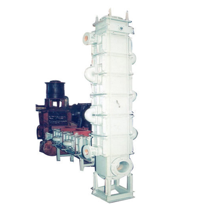
Heat exchanger series is the most advanced design of
polyblock heat exchangers. These are constructed from identically formed
impervious graphite blocks with two types of passages viz short radial
passages of 100 to 150mm length converging into a central cavity and short
length axial passages with remixing of all the axial tube fluids in a mixing
cum redistribution channel every 150 to 300 mm travel of the axial fluid.
This particular feature of hydraulic design gives abundant turbulence even
at low flow rates and enhances the 'u' and reduces the fouling & scaling
drastically. The effect of high 'u' and lower fouling coefficient 's' is
that for the same heat duty the hta value is lower. Due to their main
features of robustness, high mechanical strength and exceptionally long
working life, these heat exchangers are widely used in pharmaceutical
industries, pesticide and fumigant sectors, dye stuffs, other chemical
process industries, petrochemicals, phosphate fertilisers and pickling lines
of steel rolling mills etc.
Construction Details
The heat exchanger assembly is made from a stack of
cylindrical impervious graphite blocks, depending upon the hta requirement
and the desirable fluid flow rates.the stack of blocks is fitted with
headers at both the ends.the graphite blocks and headers are housed in an ms
shell for service fluid passage and also to impart protection and mechanical
strength to the assembly. To separate the blocks and isolate the flows,
teflon gaskets are used between each blocks. The stack of blocks is held
tightly under compressive load using disc or spring washers on long pin
bolts and nuts assembly. Deflector plates are used on entry nozzles to avoid
direct impingement. isolating bellows are require on each of the
inlet/outlet nozzles.
Application
Heat exchange between two
corrosive liquids.
Condensation of corrosive
organic & inorganic vapors.
De-superheating of vapors
Operation
Process fluid flows through the main axial passage
of the graphite header and gets distributed into multiple axial passages and
enters middle block. Then it passes through short axial passages and reaches
the mixing cum redistribution channel before entering the next block. The
same pattern is followed afterwards till the process fluid is collected by
the lower header.
Service fluid flows through the radial passages of the 1st block to the
central passage and then passes through the central passage to the second
block. Then in the second block it passes from central passage to the radial
passage and gets remixed with all the radial passages in the outer radial
recess between the graphite block and the cylindrical holder. From this
outer common channel it gets redistributed into the radial passages of the
next block. The same pattern is followed afterwards till the service fluid
is collected by the exit nozzle of the bottom holder. The process fluid and
service fluid are kept apart by teflon gaskets at the interface of each
block with the next block.
Recommended Startup Sequence
Case I. Cold fluid at wet bulb temperature.
Crack open the RT/cold fluid
inlet nozzle valve keeping the corresponding outlet valve fully open.
Let the inner contents get
flushed out and then gradually close the RT/cold fluid outlet valve
fully.
Now open the inlet valve of
the RT/cold fluid full.
Establish the flow rate of
the RT/cold fluid by gradually increasing the RT/cold fluid outlet valve
opening.
Now Crack open the hot fluid
inlet nozzle valve keeping the corresponding outlet valve fully open.
Ensure that the PRV in case
of steam is set at < 4 kg/cm2 . In case of thermostat cutoff the
temperature is set at <150°C.
Let the inner contents get
flushed out and then gradually close the hot liquid outlet valve fully
or in case of steam, leave it fully open.
Now full open the inlet
valve of the hot fluid.
Establish the flow rate of
the hot fluid by gradually increasing the outlet valve opening. or in
case of steam regulate the inlet valve appropriately.
Case II. Cold fluid at below wet bulb
temperature.
Establish the hot fluid
stream first as per the procedure given above for hot fluid (not Steam).
If hot fluid is steam, then use the procedure for startup with steam as
given above.
Establish the below wet bulb
temperature cold fluid stream flow as per the procedure given above for
hot fluid.
Manufacturers & Suppliers of
All Type Pickling Plants Required For Various Industries